Tools, parts and what you need for guitarmaking

-
Tools & Jigs
-
Tools
- Fretting Tools (Base)
- Pliers
- Sanding Blocks
- Brushes
- Files
- Routers
- Routing Templates
- Templates / Straight Edges
- Fretting Templates - Fret Scale Templates
- Clamps
- Knives
- Measuring Tools
- Tool Sets
- Reamer
- Keys, Wrenches
- Drill Jigs
- Saws
- Drill Bits
- Scrapers
- Bending Irons
- Other Tools
- Fret Hammer
- Fret Pressing
- Fretboard Protector
- Fret Bender & Tang Nipper
- ... More
- Jigs for Luthiers
-
Tools
-
Hardware & Parts
- Necks & Bodies
- Tuners
-
Hardware / Parts
- Truss Rods
- Carbon / Titan Reinforcement
- Trussrod Nuts
- Washer for truss rods
- Bridge Pins
- End Pins
- Bridges & Tailpieces E-Guitar
- Bridges & Tailpieces
- Covers
- Pickguards / Scratch Plates
- Strap Locks
- Bridge Accessories / Spare Parts
- Screws, Nuts, Washers
- Neck Attachement
- String-Ferrules
- Jack plates
- Control Plates
- String Retainer / String Trees
- knobs (pots/switch)
- Relic Parts
- ... More
- Nuts & Saddles
- Fret Wire
- Pickups & Electronics
- Materials & Supplies
- How-to
- Guitar Making
Shop Startpage Guitar Making Techniques Pickups For Accoustics E-Guit. Piezo Bridge
Construction of a Piezo Bridge
Here I show the creation of a wooden tailpiece for an electric guitar.
Guitars with the possibility of both electric and acoustic pickup are a huge asset on stage. You have the possibility to get sounds from a board guitar like from an acoustic guitar. I know of several bridges made of metal. They are available based on Fender tremolos, Gibsons LP bridges and also as one-piece tailpieces. In this article I will document the construction attempt of a one-piece tailpiece made of maple with a built-in two-piece piezo pickup. Unfortunately, I have to say beforehand that while this bridge ranked high in terms of tone, the construction around the screw-in tailpiece was not stiff enough, causing the bridge to lean in the direction of string tension after about 2 weeks. If the support area of the screws were made of metal, this effect would not occur. So, do not despair but keep trying.
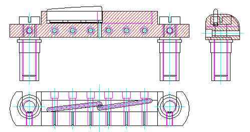
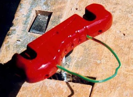
The principle:
The principle of the tailpiece is simple. Coming from the fingerboard, the strings run over a two-piece bone insert with an underlaying 3-fold piezo element. They then wind 180° around the wooden body and end in 6 string sockets of a Telecaster (receiving the string ends). The bridge body has two milled holes in 82mm distance for the screw feet of a Les Paul Junior. The pickups are connected together via a parallel circuit and preamplified by a small preamp of an acoustic guitar (9V).
 |
 |
Manufacturing Piezo Pickups (TA):
The crux for the sound I mean is to use the right piezo pickup (ceramic material). The characteristic sound of a piezo is usually rather treble-heavy and metallic, which was also the reason for a long time not to use them on metal riders as in the electric guitar. By choosing softer, filtering sound conducting materials one can influence this characteristic. If you support the strings with bone and then transmit the string vibration with wood, you have similar boundary conditions as on the acoustic guitar. Of course, this combination of materials again has repercussions on the electromagnetic properties of the guitar because of the lack of metallic hardness, but here you can compromise with a clear conscience because the magnetic PUs are extremely dominant.
Of course I don't know the results of piezo material research, so I use the well-tried acoustic piezos from a Schaller pickup (#090). Acoustic TA's almost always have the following core structure:
- 6x piezo elements, each element is only conductive on the top and bottom side.
- One-sided laminated printed circuit board (0,5mm thick) on which the piezo elements are placed in the correct distance (approx. 11mm). The lamination (copper surface) establishes the contact of the element at the bottom side.
- Around this structure a one-sided adhesive copper foil as used for shielding purposes is bent. This rectangular copper tube makes the contact at the top of the ceramics. The adhesive surface on the inside fixes the piezo elements. The printed circuit board is flush at one end and protrudes about 6mm on the contact side to create contact area.
- Single-pole shielded connection cable . This is soldered to the protruding printed circuit board and the copper foil.
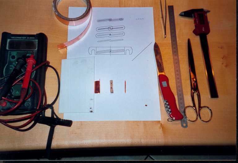 |
So TA disassembled into parts, PCB disassembled into two parts, piezo's measured and positioned on PCB. New copper foil cut to length, pre-bent on a plastic ruler and wrapped the assembly.
 |
Den TA kurz an den Vorverstärker angeschlossen um die Funktion zu überprüfen (Klopfen muss gleichlaute Geräusche ergeben), die Teilstücke auf ein Kabel gelötet und auf Paßform getestet - fertig.
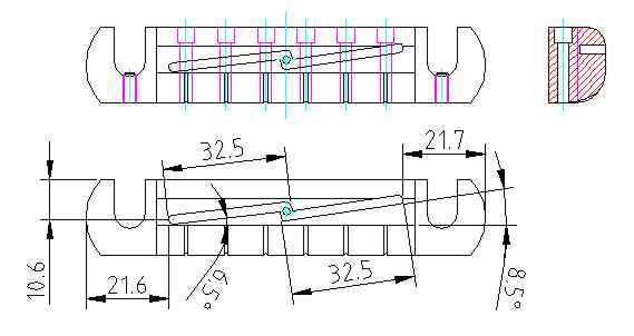
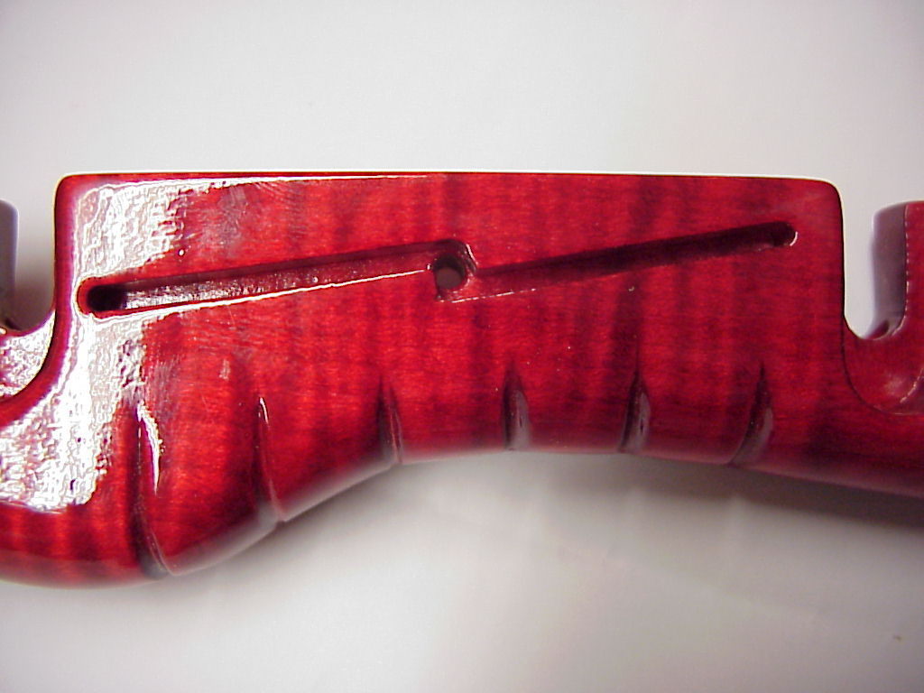
Manufacturing wooden body:
Since I had drawn the design beforehand, I made a template of Plexiglas around which I could mill with the thrust ring of the router, I also chamfered the groove for the piezo channel with it. To get an optimal force distribution, I chose close-fitting annual rings and about 45 ° in neck direction inclined growth rings.
 |
 |
 |
 |
|
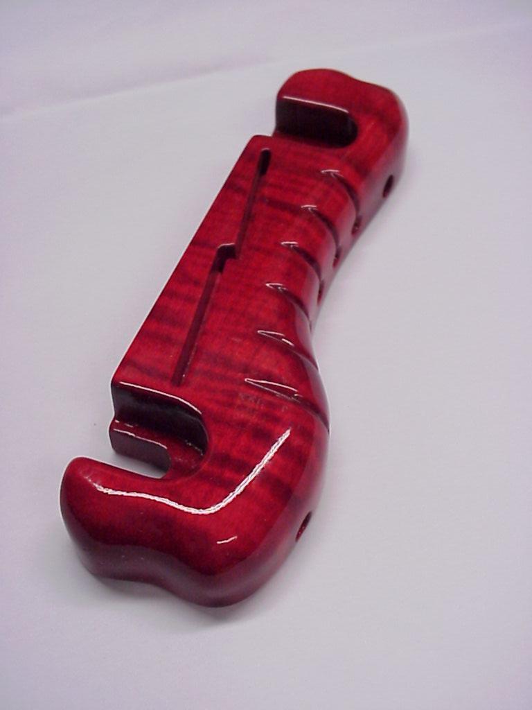
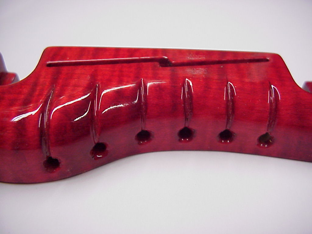
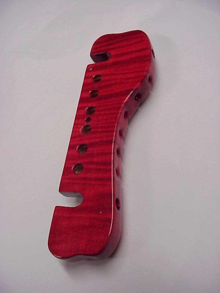
While I was still preparing the wood, I didn't like the simple from anymore and decided on what you see in the photos. After the shape was worked out, I drilled the string holes, then the holes for the bushings. For the set screws to adjust the string compensation, I used M3 set nuts. For routing the 2.5mm wide channel, I taped the template to the underside with carpet tape, mounted a straight pin of the same thickness as the router itself on the base, and was able to router very accurately following the template after piercing the router bit. The string guides I still notched with a knife and with sandpaper I rounded the whole thing and off it went into the surface.
 |
 |
 |
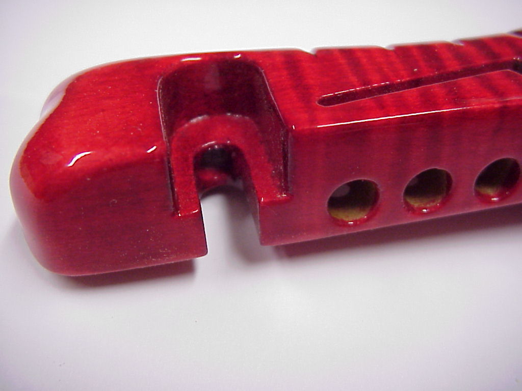 |
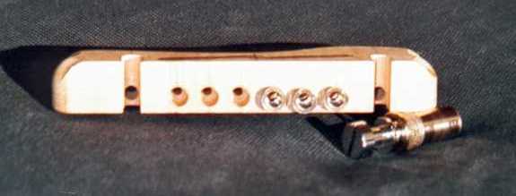
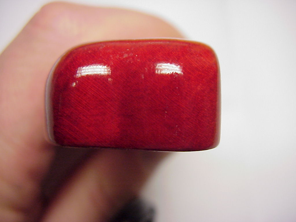
In the photos you can see details even before polishing.
 |
 |
 |
Since the strings must be grounded against hum, I glued small strips of copper foil in the sleeve holes and let them protrude 5mm on the underside. As a cross connection I glued another 3mm strip over all 6 strips and soldered them, also with the shielding of the connecting cable. The sleeves were now pressed in, the setting nut set, the piezo positioned, bone pieces inserted.
I built the finished TA into a prototype, strung them, set the compensation, wired the thing and was already excited! The sonic result was outstanding! Very natural reproduction. But unfortunately, as I wrote at the beginning, the bolts pressed into the wood and the TA lowered after 2 weeks, so I was not comfortable and I mounted a LP Jinior Bridge.
Result:
Sound result as expected, much learned! Try again with stronger materials, possibly reinforce insert holes or make a sandwich of metal and wood.
 |
Last modified on 16.04.2001

|
Rall Guitars & Tools Hauptstrasse Tel +49 (0) 8803-48856-56 Retail Shop: By appointment only
|
Subscribe our Newsletter By subscribing our newsletter you accept our Privacy Policy and Terms and Conditions. |